|
THE WORLD'S SMALLEST WIND TUNNEL |
|
EXHIBITS |
|||||||||||||||||||||||||||
|
EXHIBITS FRIENDS HERITAGE HOME LIME PARK OPEN DAYS PARKING TECHNOLOGY |
|||||||||||||||||||||||||||||
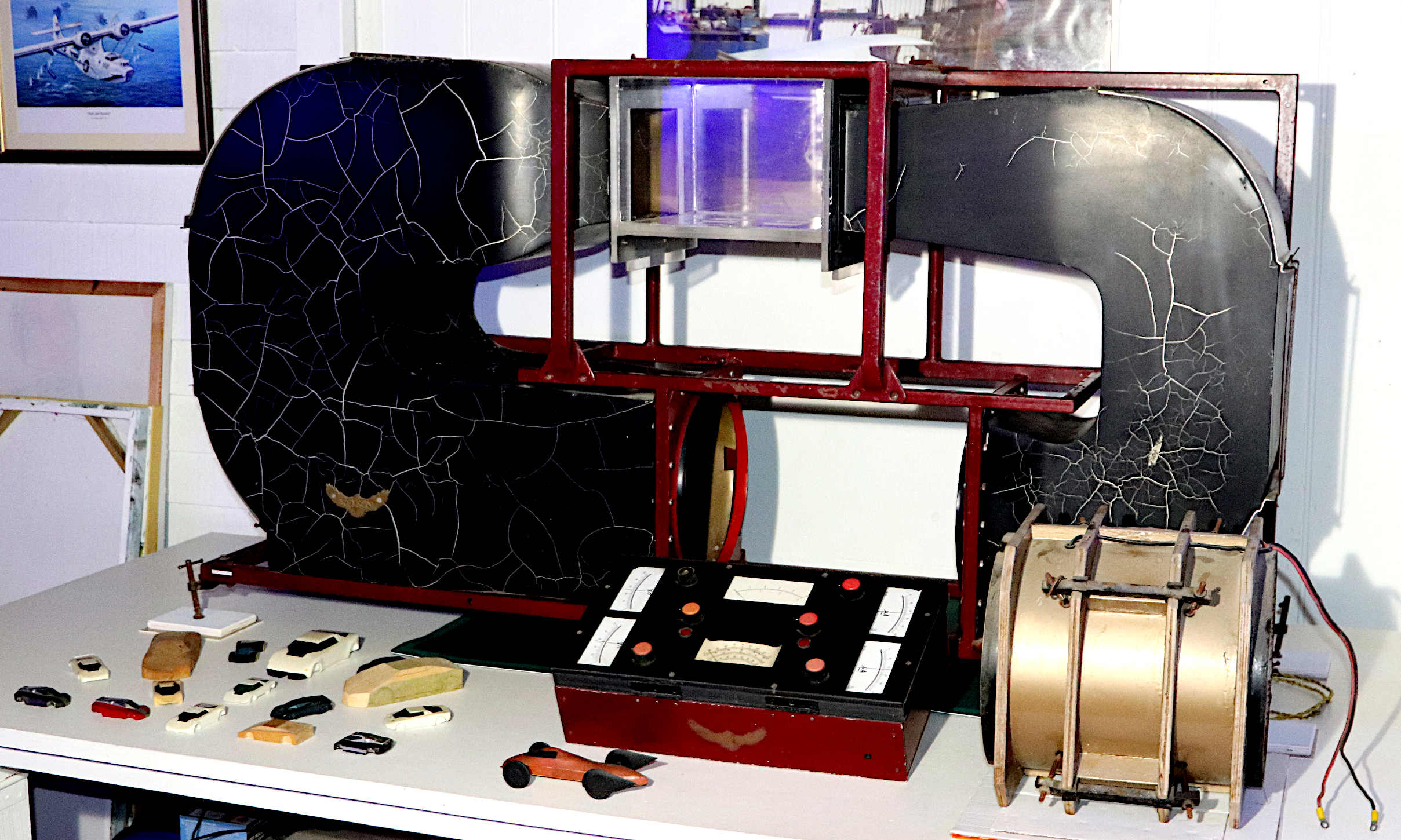
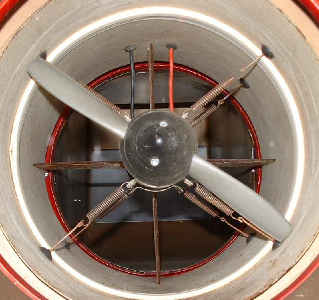
RESTORATION - Presently the subject of a service and clean, this is the wind tunnel in the Museum in September 2023. The model used in the design of the Bluebird Electric 1, is seen in the foreground in brown modeling clay @ 1:24th scale. Over the years, the paint on the aluminium tunnel has crazed, where it was coated in epoxy resin, and then matt black, and the expansion coefficients in winter and blazing summer heat are different. The machine is still operable. The fan unit was tested on the 21st.
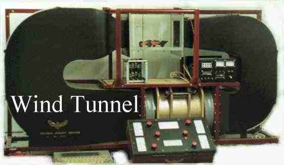
The MKII wind tunnel assembly, with the BE1 test model in the visualization chamber in the 1990s.
Not directly connected with the generating history of Herstmonceux Museum, though designed and constructed in the workshop garage, in Lime Park, as a way to visualize and measure the efficiency of a vehicle shape, in the ability to pass through air, with the least resistance to movement.
This was the second compact re-circulating wind tunnel to be built in this location. Designed to be a desktop machine, it is that small.
You do not have to spend a fortune to construct a very basic wind tunnel. The first was made of plywood, and recycled materials, including the fan and motor, costing something like £10 in materials. At hobby or school level, cardboard can be used, and cheap blades, where low air speeds don't matter. It is only when more accurate results are needed, and higher airspeeds, that it is worth moving to electronics.
Try putting your hand out of a car sunroof (only when safe to do so, and never a window), aiming your fingers into the wind. You can hold your hand there with no problems. Then put you hand flat to the wind, and feel the difference. Your hand will be blown backwards, much harder. Without any instruments at all, this simple experiment reveals the basics of all aerodynamic design.
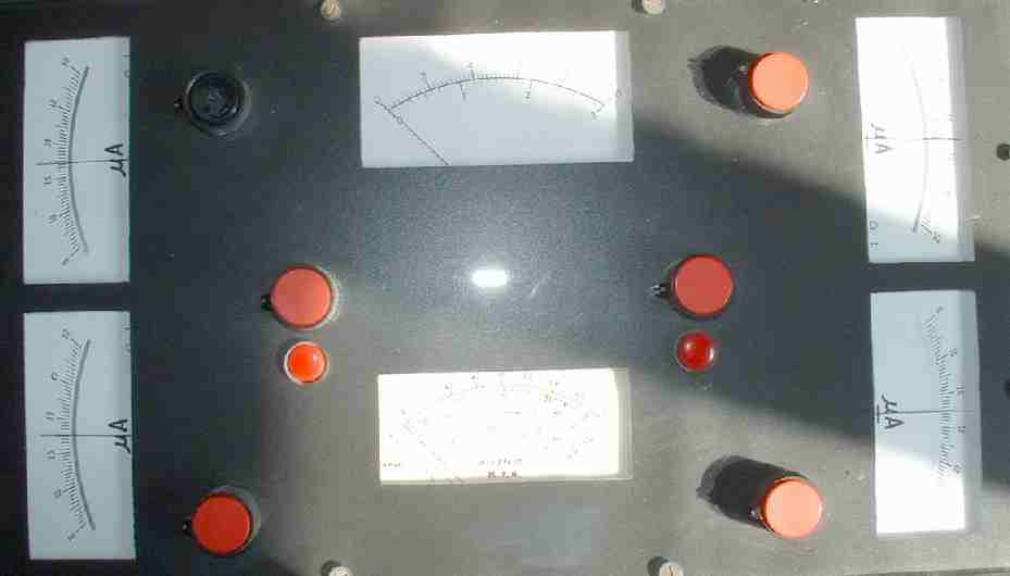
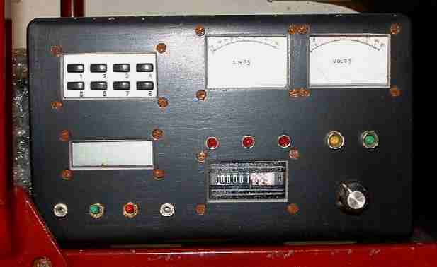
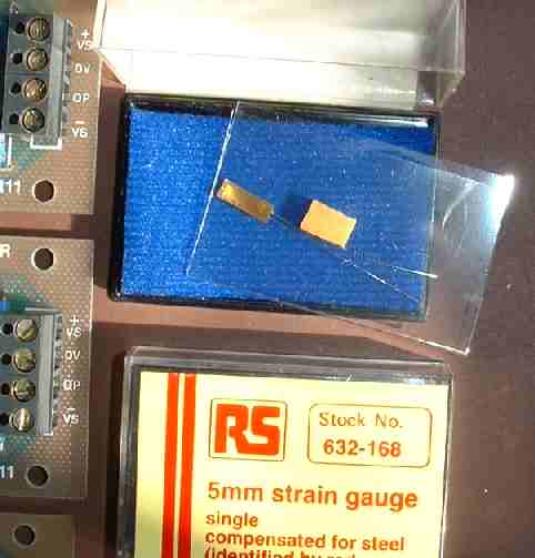
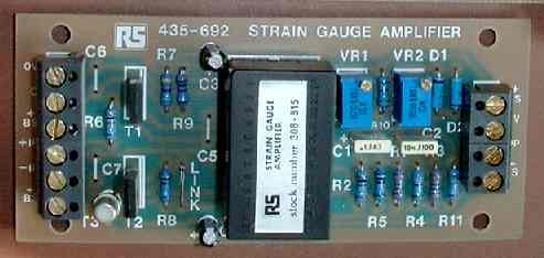
Electronic strain gauges simply allow engineers to measure drag, lift and down-force (see pictures below) with more accuracy. In this case with a five element balance. A turn table was incorporated so vehicle models could be tested in side wind conditions. Air temperature and wind speed were also monitored and smoke could be trailed over models to visualize airflow, to highlight problem areas. This instrument measured just 60" x 40" x 15" (1524 x 1016 x 381mm). Being a closed circuit design it was not unbearably noisy in operation.
This wind tunnel exhibit is a relatively complex piece of engineering, ideal for engineers working on a Masters Degree thesis, or other higher learning projects.
The Wright Brothers were the first inventors to use such a tool to compile lift and drag tables for various wing shapes. It is much more difficult to design a "balance" to measure lift and down-force on each wheel of a vehicle, than a tunnel to measure lift on a wing. When working at such a small scale, accuracy of measurement is essential. Fortunately, electronics come to the rescue, with compensated amplifiers providing multiplication of needle movement up to a thousand times the original voltage variation, as a resistive foil is stretched or compressed.
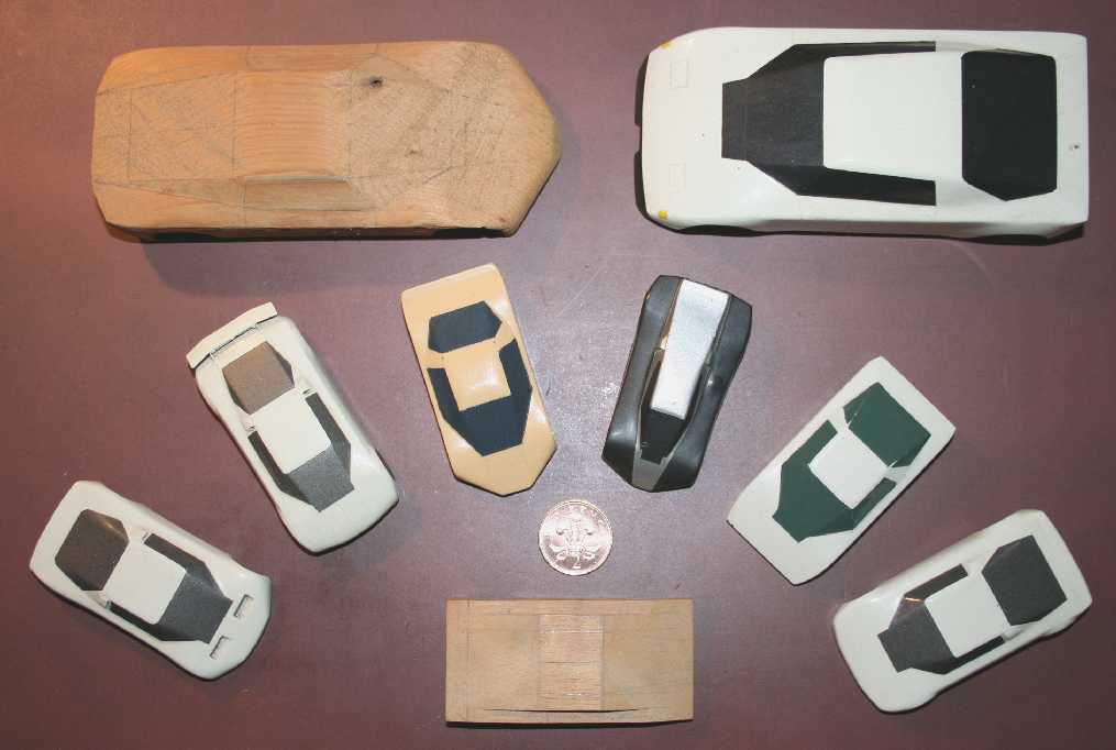
Some of the wind tunnel models on display at Herstmonceux Museum, the larger ones for use in the MKII measuring instrument were 1:24 scale. The smaller models were 1:50 scale. These were hand carved in wood, then painted to as near as possible present a surface finish representative of a full size vehicle. The rough grain of wood, would not have worked so well. These models were carved in the Lime Park workshops.
Having made a model of the vehicle you want to test, you need to work out the frontal area. This is easy in AutoCad. The frontal area should include all appendages (wing mirrors) and the wheels. A base card of the same frontal area is then used to calibrate the wind tunnel. Or, you can do this mathematically. Either way, the wind tunnel has to be calibrated. A flat plate is taken as 1.25 or thereabouts.
A wind tunnel is a research tool developed to assist with studying the effects of air moving over or around solid objects. The most famous early experimenters to build a wind tunnel were the Wright Brothers, Orvill and Wilbur. They used their tunnels to design wings, to calculate the lift of different airfoil sections, thus the wing area needed, to lift their biplane off the ground at Kitty Hawk at different speeds.
One of the main factors affecting top speed, or fuel consumption of a car, is the drag of the vehicle. This is determined by the shape of the vehicle's body. How slippery it is might mean a faster vehicle, such as in racing competitions, or how much it will cost to operate, to drive to the shops and back. Unlike the Wright Brothers, we don't want a car to take off, except in a James Bond movie. But how can we measure how well a car moves through the air, and the lift or downforce of a body shape?
Well, apart from a wind tunnel, you also need an accurate model of the vehicle you are proposing to build. Small enough to fit inside the measuring chamber of any tunnel. Hence, the size of your models, determines the size of your wind tunnel, and vice versa, the size of your tunnel, determines the size of your models. The bigger the model, the bigger the tunnel. Most car makers use full size vehicles, in very large wind tunnels, the size of a giant car park. Imagine the cost of that. It is many £millions of pounds.
The wind tunnel above cost around £8,000 to develop in the 1990s, about £30,000 adjusted pounds today (30 years later). It took a little over 6 months, including designing the frame, fan housing, ducting, and measuring instruments. Three months conceptualizing and drafting, and three months actually building the machine, welding the mild steel frame, cutting and welding the alloy sheet, some of which work was completed at Filching Manor Motor Museum, near Polegate. Mostly, the plexiglass chamber was fitted in Filching. The electrics and electronics were wired up in Herstmonceux.
The design was an improvement on a smaller plywood version, with an oil bath float, on which the smaller model vehicles were mounted, facing into the wind, only measuring drag. The machine above measures lift and downforce on each wheel of a model, and the subject vehicle can be rotated to simulate sidewinds. Unfortunately, the original wooden version was scrapped. A real shame for the Museum, to be able to show progression.
The other major component of vehicle drag, is the rolling resistance of the tyres, including the driveshaft and wheel bearings. Meaning that thinner wheels and tyres, and higher pump pressures, will all reduce rolling resistance, and improve MPG. The road surface is also important. Smooth tarmac is much easier to travel over than sand. Concrete increases rolling resistance, compared to tarmac. Many land speed records are run and records set on dried salt. Such as the famous Bonneville Salt Flats, Utah, USA.
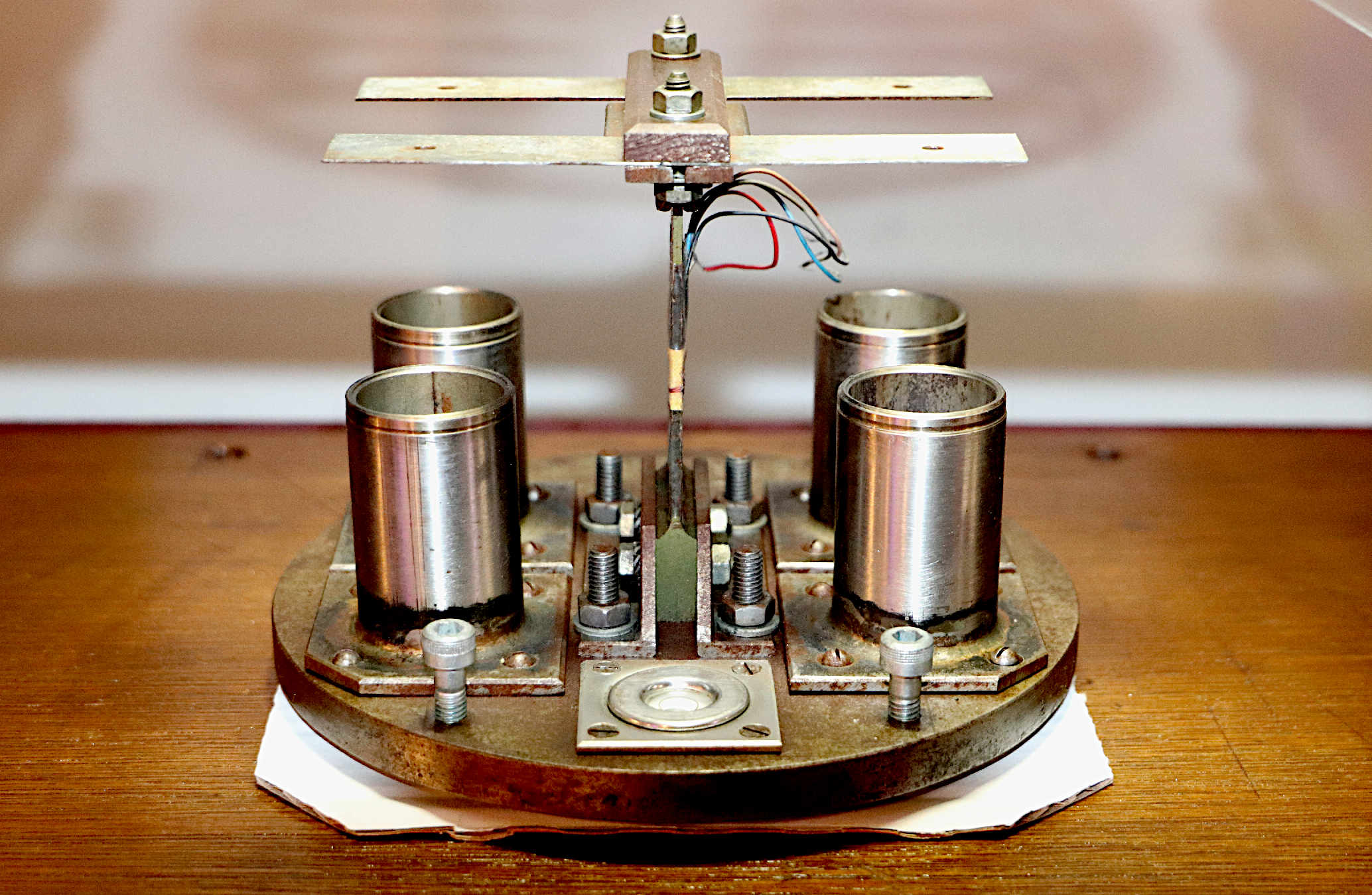
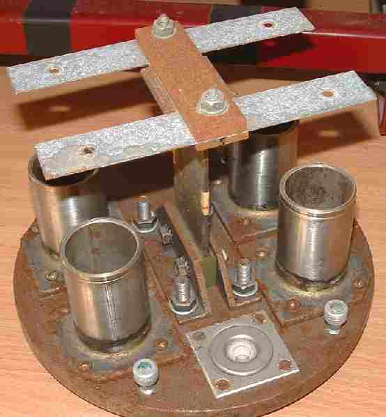
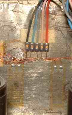
5 ELEMENTS - This is the business end of the wind tunnel, a five element strain gauge (beam or balance) arrangement, that measures drag, lift and downforce on each wheel. The pushrods of the assembly are not shown in this picture. There are four stainless steel cylinders below each wheel gauge. The cylinders are oil filled, to damp the vibrations, helping to stabilize readings. The pushrods go from a piston in the cylinders, through the wheel element beams, to a Plexiglas pad in the visualization chamber. The whole unit is adjustable on screw threads, with a built in level, and may be revolved. The model being tested has steel inserts in the wheels, that clamp to the pushrod pads electro-magnetically. It's a bit rusty, but not bad for 30 years unpainted. Copyright photograph © Herstmonceux Museum, 28 September 2023.
A
CONTROLLED AIRFLOW
The drag coefficient Cd is equal to the drag D divided by the quantity:
air density r times reference area A times one half of the velocity V squared.
Table approximations, one from NASA. These are assumptions, guesstimations that can be made, while you work out the details of your own method of calibration. Ideally, you should test a flat plate, sphere and airfoil. All of the same frontal area. That should give you 3 relatively reliable datum points on your meter display. Be sure to use the same airspeed when taking measurements.
WIND TUNNEL HISTORY
Alongside, the world's smallest water basin, the Museum is home to some interesting technological exhibits, many world record contenders.
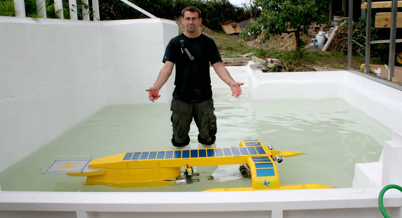
THE WORLD'S SMALLEST WATER BASIN - Project director, Chris Close, after a day testing the SeaVax in an open air water basin. On this day in 2016, the 29th of July, the proof of concept model, cleaned microplastic from the test tank, collecting the litter in her hydro-cyclonic filters. The total cost of building the 2.1 meter (fully functional) model was around £120,000 pounds. Test tank costs, added to the project cost, but not prohibitively.
There are several innovative vehicles and vessels on permanent display at Herstmonceux Museum, including:
1. Art Gallery - Collection of paintings, pictures, graphics, sculptures, wooden carvings & exotic glassware 2. Archives - Historic documents library, patents, trademarks, copyright, films, catalogued legal papers & letters 3. An Edwardian ice well, throwback to the days before refrigeration 4. A large underground (condensation/cooling) and water storage chamber for ice making 5. The world's smallest water basin, test tank for model boats & ships to 1:20 scale 6. World's smallest wind tunnel, vehicle drag measuring instrument using electronic strain-gauges 7. Three PV boat models, Navigator, SWATH & 2 cats + route map prior to Swiss PlanetSolar 8. Seavax, the ocean cleanup proof of concept prototype from 2016 - Hall of Plastic, ocean waste, marine litter Vs fish 2050 9. AmphiMax, radio controlled (working) beach launching & recovery vehicle for SeaVax 10. Anthony the most dangerous giant Australian bulldog ant, 300 times normal size - Making Ant's Cart 11. EV - FCEV refueling station model in 1:20 scale 12. The only working (fully functional) water well in Herstmonceux village 13. The fountain of youth, supplied from natural well water drawn on site 14. Second World War, 'Anderson Inspired,' bomb proof shelter constructed by Major Charles de Roemer 15. City sports FCEV-BEV, hydrogen gull wing proof of concept DC50 electric car 16. Land speed record car: Bluebird-Electric BE1 (original 1st) with battery cartridge exchange 17. Land speed record car: Bluebird-Electric BE2 (original 2nd) with cartridge exchange 18. A complete mummified squirrel, found when re-roofing the Museum June 2017 19. A fully operational, and restored VW Kombi van dating from 1978 (historic vehicle) 20. BMW i3, battery electric vehicle hybrid, with onboard generator range extender 21. Solar panel, and battery energy storage systems facing north-south and east-west 22. A hornet's nest found on site & preserved in 2016 (reported as [Asian] invasive species, to be safe) 23. Three sewing machines, including an antique Singer and a Brother industrial. 24. Adventure climbing frames for children (back to nature) Swiss Family Robinson 25. 'Elizabeth Swann' proof of concept model 1:20 scale hydrogen powered trimaran 26. Holm oaks, planting and growing trees from acorns on site, re-wilding in Sussex 27. Robotics, mechatronics, electronics and animatronics display - the steel frame, head/jaws, & drives of Anthony (coming soon) 28. Dalek - Full size, drivable working model of the famous Doctor Who BBC TV series, and Peter Cushing film 29. Films - Library of VHS tapes, DVDs and BluRay classics, national treasures, greatest hit, noir, oldies - from 1920 30. PartArt4OW - Proposal for an adapted & illustrated version of the Kulo-Luna script, with local exhibit & art competition 2025
|
|||||||||||||||||||||||||||||
|
|
|||||||||||||||||||||||||||||
|
EXHIBITS FRIENDS HERITAGE HOME LIME PARK OPEN DAYS PARKING TECHNOLOGY UNESCO
Copyright © 2023 - 2025 Lime Park Heritage Trust. A not for profit organisation with charitable objects.
|
|||||||||||||||||||||||||||||